Transforming Japanese Beef Retort Accou Robot Watch
It was a common cold January Saturday night in Chicago and nosotros had big plans. Buddy Guy'south Legends bar was packed. We setup directly under one of the PA speakers less than fifteen′ from the stage. Time to celebrate. Skip the glass, ane pitcher each and keep them coming. We're about to make bootleg recording history. Conversation evolved into bloviation on what our cover art would look like, certainly it would be a photograph of our battery powered tube mic pre-amp recently created in my basement lab. We had four hours to kill before Buddy's appearance. Our rate of Goose Island and Guinness consumption would put u.s.a. at three-sheets to the wind by 11. Must focus. It's time, Buddy was on. Much fumbling about and forgetting how to plow on the Japanese-made 24 flake digital recorder with its nested LCD menus, cryptic buttons, and late 90's firmware. Make it work. We did, just in fourth dimension for the bouncers to notice the nail mike and battery packs. Wait, wait… perhaps we should talk about why tube amps are worth this kind of trouble first.
Yep, vacuum tubes practise sound ameliorate than transistors (before you hate in the comments check out this scholarly article on the topic). The difficulty is cost; tube gear is very expensive because it uses lots of copper, iron, often signal-to-point wired by hand, and requires a heavy metallic chassis to support all of these parts. But with this loftier cost comes skillful economical justification for building your ain gear.
This is 1 of the last frontiers of do-it-yourself that is actually worth doing.
Vacuum tubes work by thermionic emission, pregnant that electrons are emitted by something really hot under vacuum. In this case a lightbulb filament or a lightbulb filament that heats up a cathode metal plate encircling the filament. These electrons are accelerated from the cathode to the plate, thereby flowing electric current from the cathode to the plate. This electric current is controlled by a control grid, literally a small wire mesh between the cathode and the plate that looks like window screen. For applied purposes the grid is similar to the gate of a field effect transistor although the physics are completely different. There are some enthusiasts who actually make their own tubes from scratch.
It is easy to get sound out of vacuum tube audio circuitry. Tube circuits lend themselves to self biasing and simple first-social club approximations. Buy parts today and listen to Jimmy Hendrix by Sun evening.
How a uncomplicated single-stage tube preamplifier works
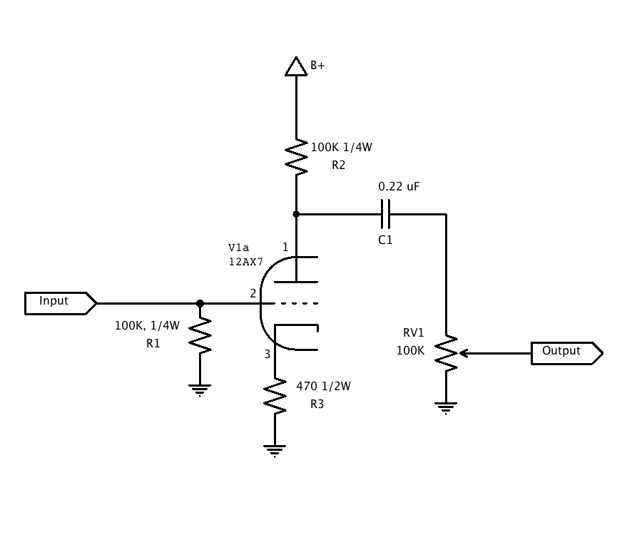
The audio input is fed directly into the grid of V1, which is also shunted with resistor R1. R1'southward job is to both pull the filigree of V1 to 0V potential and besides provide a termination impedance to the audio input (in most cases 50K or 100K). R2 and R3 ready the gain and bias point. A unproblematic approximation for voltage gain is R2/R3 assuming the tube has a 'high mu.' mu is a measure of transconductance or the tube's power to amplify, in other words current output/voltage input. Current flowing through the tube sinks a current beyond R3. This voltage across R3 while this excursion is idling (or not amplifying) is equal to the bias voltage. This configuration is known as 'self biasing.' Erstwhile-salt engineers will tell y'all that designing with tubes is easier than transistors. They're right.
The output is Ac coupled with C1 to block the plate voltage from feeding into whatever this circuit is wired to. Similar a single-stage transistor amplifier the output is inverted, a rising voltage at the grid results in a falling voltage at the plate.
Power it
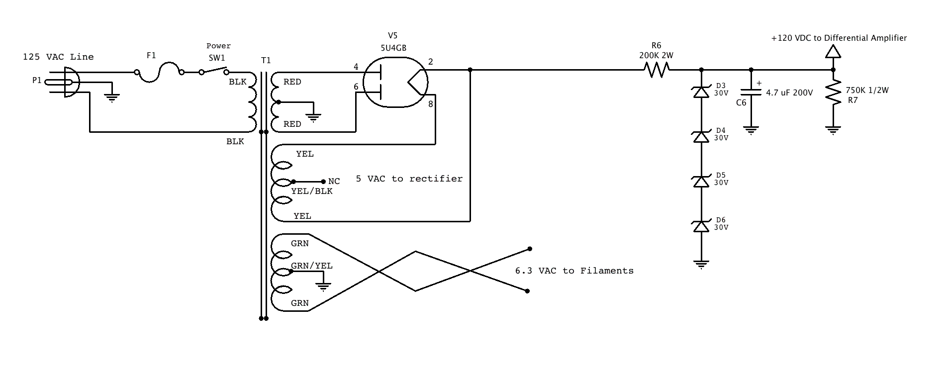
You volition need 50-150V of B+ (or plate voltage, because it is connected to the plate of the tube via R2) and virtually 1 mA to ability this preamplifier. Yous can achieve this with the following excursion that supplies a regulated 120 VDC using zener diodes.

Information technology is important to note that tubes are high voltage low current and from a conventional/modern circuit design perspective the resistors seem very loftier, caps low, and current regulation approaches amateur at best. This power supply works because we only need 1 mA.
Brand 2
Connect the inputs to your audio source and the outputs to your favorite solid country amplifier. Nosotros at present have a 'hybrid amplifier,' containing a tube front-end and a solid-land dorsum end. Professional versions of this amplifier are for sale by a large consumer electronics manufacturer.
Take it on the road, a true story from my college feel

So back to the story I started before. My bootleg conspirators and I were well lubricated and near to get the best recording of a live concert to date when we were stopped by the bouncers. After a short interrogation we were booted out, dorsum onto the common cold streets but with a feeling of satisfaction that, although we did not record the prove, we had the best audio gear in town:
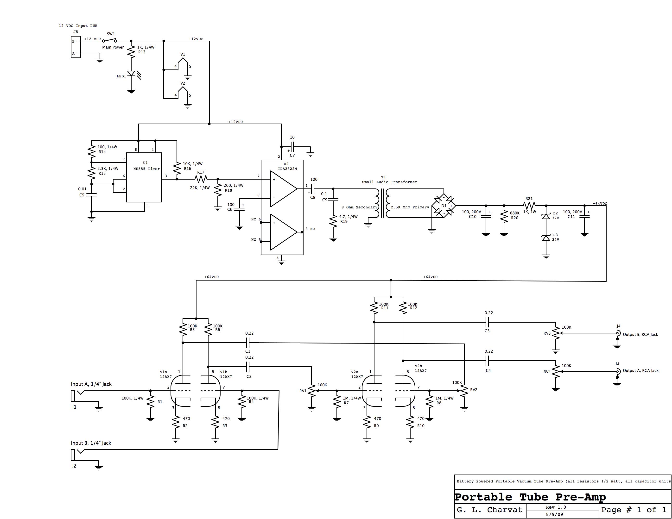
In this design, ii pre-amplifiers described in a higher place are used with a battery powered high voltage supply. The high voltage supply works by creating a square wave with a 555 timer. This square wave is in a higher place audible frequency, effectually 40 Khz. The square wave is fed into a small sound power op-amp. The output of this op-amp is back-fed into the secondary of an audio output transformer, generating high voltage AC 170V at 40 Khz. This signal is rectified, filtered, and regulated in a conventional sense. The entire system runs on 8 AA batteries and should operate for approximately iv hours continuously. Everything yous need to make your ain is hither in this PDF.
Power Amplifiers
Somewhen you may want to create a power amplifier. In that location are a number of classes and variants of tube audio power amplifiers:
- Class B are push button-pull amplifiers, similar to conventional solid country amplifiers, where in that location is a pushing tube and a pulling tube being driven 180 deg out of phase.
- The class AB is biased so that the output devices are on all the fourth dimension, thereby reducing or eliminating cross-over baloney which occurs when one tube hands the load off to the other.
- Class A amplifiers are basically a loftier power version of our pre-amp in a higher place, where instead of resistor R2 we have an audio output transformer. Lots more than power is burned needlessly in Class A amplifiers because they are e'er on, they either allow go of the load or pull it closer to 0 potential. When not doing anything they sit half-mast, burning lots of power. Many prefer class A because there is no cross over distortion and they are very unproblematic to design.
- More obscure types of amplifiers include transformer-less, where lots of tubes are in parallel in a Class A configuration to direct drive a 4-eight ohm loudspeaker load.
Almost all tube amplifiers require a transformer to match the high impedance of the tubes (3K or so) to the depression impedance of mod loudspeakers (iv-8 ohms).
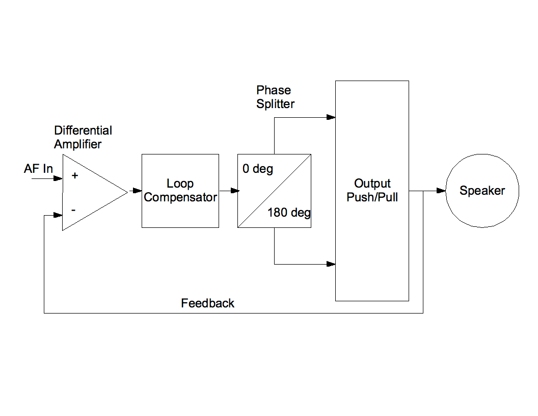
Feedback tin exist applied to all amplifier types, where only like an op-amp excursion some of the output signal is fed back to the input, allowing the amplifier to compensate for non-linearities. Feedback provides a much cleaner signal and improved performance. This is not e'er desirable depending on your goal. Without feedback expect on the guild of 7% full harmonic distortion. With feedback and loftier gain expect 0.5% total harmonic distortion.
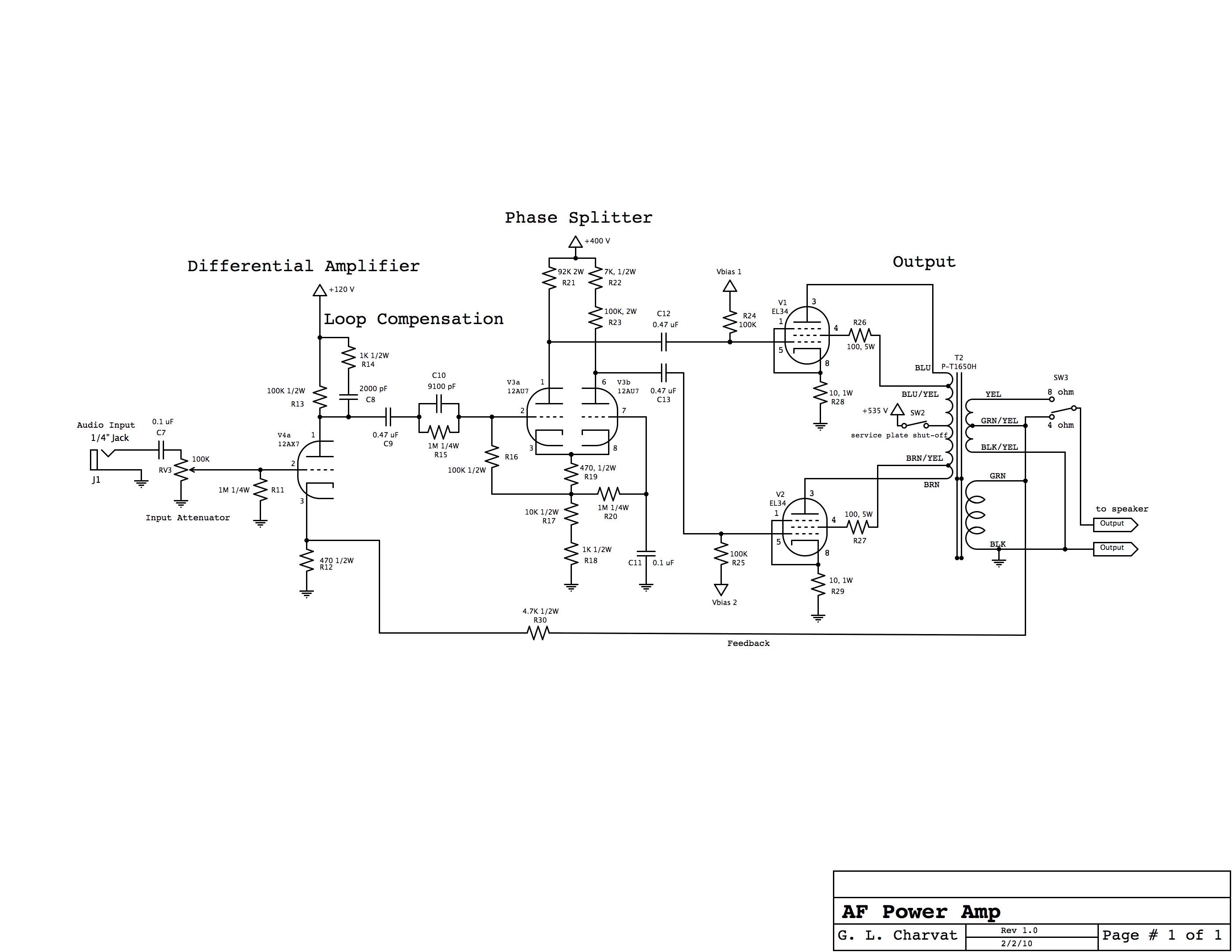
A typical tube power amplifier is a class AB with feedback. In this, there is a proceeds phase that also functions every bit the differential amplifier when feedback loop is closed. This is followed by what is known as a 'phase splitter,' which is basically a buffer or small amount of proceeds using two triodes providing both in-stage and out-of-phase output. The two outputs drive the output ability tubes at 0 and 180 deg phase respectively. The output tubes push button and pull on the output transformer. Tubes can only pull, so the output transformer is powered from a center tap on its primary winding. Finally, the output is fed both to a loudspeaker and through a feedback network to the first stage.
A working example of this is shown in the schematic with details on its implementation (PDF).
Tube home theater
With these pre-amplifier and ability amplifier circuits yous can scale your blueprint to a complete dwelling house theater organisation with 5.1 sound. For technical details of its implementation, check out this PDF. You can also check out my project which was featured early terminal yr.
Let them shine

Just like the reality Tv shows where skilled craftsman make motorcycles or hot rods you likewise tin customize the wait of your tube amplifier. Place the tubes on the top of the chassis so you can watch them glow. Co-locate the output, power, and chokes on top every bit well. It's fun to watch them glow in the dark while playing 'Dark Side of the Moon.'
Where to find parts
Sound tubes are easy to find and continue to exist manufactured in Eastern Europe, Russia, Cathay, and others. Transformers of all types including audio output and power are readily available through Hammond Manufacturing and other sources. A new movement in the tube audio community is to find obscure pairs of output transformers and make unmarried-ended non-feedback amplifiers. Recently, manufacturers take started to remanufacture loftier voltage axial leaded caps and other old-school parts. You lot can find this stuff at Antique Electronics Supply, Just radios, and even Mouser and Digi-Key (less expensive for aforementioned stuff but requires a lot of filtering and digging through the itemize).
Larn fast
There's a lot of fabric on tube design, just these are my personal favorites:
- Radiotron Designers Handbook.
- Principles of Power.
- Where some of the tube audio community gathers, audioXpress Mag.
Try vacuum tubes in your side by side sound projection. Go along those filaments lit.

castellanosiounincid.blogspot.com
Source: https://hackaday.com/2014/06/04/keep-those-filaments-lit-design-your-own-vacuum-tube-audio-equipment/
0 Response to "Transforming Japanese Beef Retort Accou Robot Watch"
Post a Comment